In
a Heterogeneous Network (HetNet) introduced
in 3GPP Release 10, low power nodes (LPNs)
such as RRUs/RRHs, Pice cells, femto cells, and relay nodes are deployed in a
macro cell.
Small cells
are primarily added to increase capacity in hot spots with high user demand and
to fill in areas not covered by the macro network – both outdoors and indoors.
They also improve network performance and service quality by offloading from the large macro-cells.
The result is a HetNets with large macro-cells in combination with small cells
providing increased bitrates per unit area.
Cell Range Extension
A
major issue in Hetnet planning is to ensure that the small cells actually serve
enough users. One way to do that is to increase the area served by the small
cell, which can be done through the use of a positive cell selection offset to
the the received power of the small cell. Extending the coverage of a cell by
means of connecting a UE to cell that is weaker than the strongest detected
cell is referred to as cell range extension.
In
a network, with all cells using the same frequency (frequency reuse = 1), the
UE normally camps on a cell with strongest received DL signal (SSDL); hence the border
between two cells is located at the point where SSDL is the same for
both the cells. In homogeneous networks, this also typically coincides with the
point of equal path loss for the UL (PLUL)
in both cells.
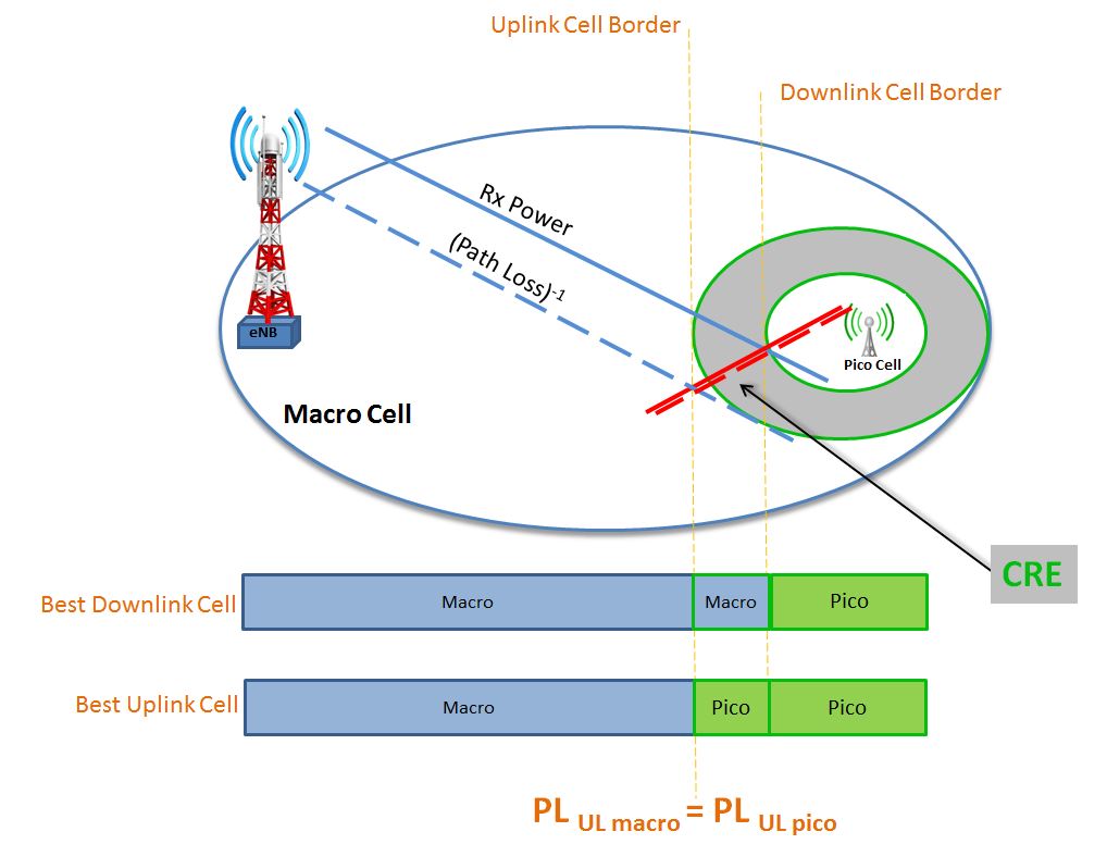
In
a Hetnet, macro cell transmits at a very high power as compared to LPN. So, as
shown in the figure below, there are two borders, a Downlink cell border which
is defined by SSDL and an Uplink cell border which is defined by PLUL.
In the Downlink, SSDL observed
from the macro cell and the pico cell are equivalent at a location that is
closer to the pico cell, which forms the Downlink cell border. On the other
hand, the location where path loss to macro and pico cells is equivalent is far
from the pico cell. This is due to the fact that the UE transmission power is
same whether the UE is being served by macro cell or pico cell.
In
a normal case without CRE feature, the serving cell choice for the UE is based
on the DL received power. With CRE, a positive cell selection offset is
added to the SSDL of the small cell to increase the range served by
small cell. So, more UEs are attracted by small cell as compared to the case
without CRE which greatly increases HetNet efficiency.
In CRE (gray region) in the figure above, the UE does not necessarily be served by the eNB that has the strongest DL received power.
In CRE (gray region) in the figure above, the UE does not necessarily be served by the eNB that has the strongest DL received power.
In
addition to the advantages of increasing HetNet efficiency, offloading macro
cell’s traffic, CRE has another advantage of reduced Uplink interference in the
system. A UE without CRE, served by the macro cell closer to the pico cell
border, would be transmitting at a higher power and interfering with the uplink
of small cell. With CRE, the same UE is likely to be served by closer cell (small
cell) with lower path loss reducing the need for the UE to transmit with such a
high power.
As
discussed already, the range of the small cell is expanded by implementing a
selection offset (UEs in idle mode) or handover threshold in measurement configuration
(UEs in connected mode) in the favor of the small cell.
UEs in Connected Mode
A
connected mode UE may be configured with cellIndividualOffset
as defined within measObjectEUTRA corresponding
to the frequency of the neighbor cell. Measurement events that are influenced
by this parameter are A3, A4, A5 and A6.
This
parameter is applied individually to each neighbor cell with load management
purposes. The higher the value allocated to a neighbor cell, the “more
attractive” the cell will be.

As an example
for event A3, (not considering other offsets and hysteresis), the event
entering condition is fulfilled when;

where Mn
and Ms are measurement result of the neighboring and serving
cells respectively. So, the more the value of
UEs in Idle Mode
In
Idle mode, mainly, parameter q-OffsetCell
within IntraFreqNeighCellInfo (in
SIB4) and within InterFreqNeighCellInfo
(in SIB5) used for cell range extension purpose. This parameter is mainly used
in cell-ranking criterion for neighbor cell.

Drawbacks
Having
discussed the benefits of CRE feature, a major drawback of this feature is that
in the CRE zone, the UEs are forcibly being served by the small cell, but in
reality, the downlink received power from the macro cell is higher than the
small cell. So, there will be severe downlink inter-cell interference from the
macro cell to UEs receiving transmissions from a pico cell i.e., the SINR at
the UEs in CRE which is being served by small cell is below 0 dB. This may impact the reception of
the DL control channels in particular.
A
number of features added to the 3GPP LTE specifications can be used to mitigate
the above-mentioned interference problem in HetNets with small cells. These
features will be discussed in detail in further posts. Usually CRE is jointly designed
with ICIC/eICIC/FeICIC schemes/features to mitigate this interference problem.
Reference:
3GPP TS 36.300, 36.331, HetNet
AOA,
ReplyDeleteSir at one place your mention that "UE transmission power is same whether the UE is being served by macro cell or pico cell"........ while in other place you mention that " A UE without CRE, served by the macro cell closer to the pico cell border, would be transmitting at a higher power and interfering with the uplink of small cell."... so which one is correct? user transmitting with same power or different power in uplink???